Camera calibration is a very important step, it is necessary to get the relationship between the object coordinates and the image coordinates. With known parameters of the camera model, including internal parameters and external parameters it is possible to determine this transformation. Calibration is used to determine this parameters. Camera matrix is one of the important internal parameters and position and orientation of the sensor to the world coordinate system are some of the important external parameters.[1]
In order to calculate the ground displacement from displacement between frames is necessary to know the relationship between the image size and the field of view size. Knowing this relation it is possible to calculate the real ground displacement at a given distance from the ground. The field of view is obviously dependent of the distance of the camera to the ground and for a better result it is essential to know this distance.
Therefore in a real implementation a method of estimating this distance should be available. In this work the test will be carried out with the help of a industrial robotic manipulator and his position will be used as ground-truth.
The experimental procedure proposed will require that the sensor is parallel to movement, the image being 1-D brings difficulties to assure that. To assure that the sensor is parallel to the movement a calibration method suggested by [1] [2] is used. The method implies the use of a pattern of vertical parallel lines crossed with diagonal lines, parallel with each other (figure 1)
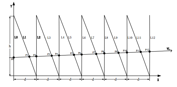 |
| Figure 1 - Pattern used for line scan cameras calibration [1] |
With this configuration it is easy to see that when the camera is completely horizontal the spaces between the pairs of lines will have an equal distance, and when the camera is oblique this spaces will have a tendency to increase or decrease depending on the orientation of the sensor.
In the figure 2 is possible to see a image of the process of calibration, the image shown here is the representation of 480 repeated lines since the camera has not moved. The camera is adjusted until all the distances between the pairs of lines are equal. Once that is accomplished, the camera sensor is horizontal to the pattern and therefore horizontal to the movement.
 |
| Figure 2 - Image taken during the process of calibration. |
[1] - "Line scan camera calibration for fabric imaging" by Zuyun Zhao
[2] - "Calibration of Line-Scan Cameras" by Carlos A. Luna, Manuel Mazo, José Luis Lázaro, Juan F. Vázquez
No comments:
Post a Comment